RF Plasma Propulsion: How Radio Waves Become Spacecraft Thrust
What VASIMR actually does, what the test data prove, and why the spacecraft is harder than the engine

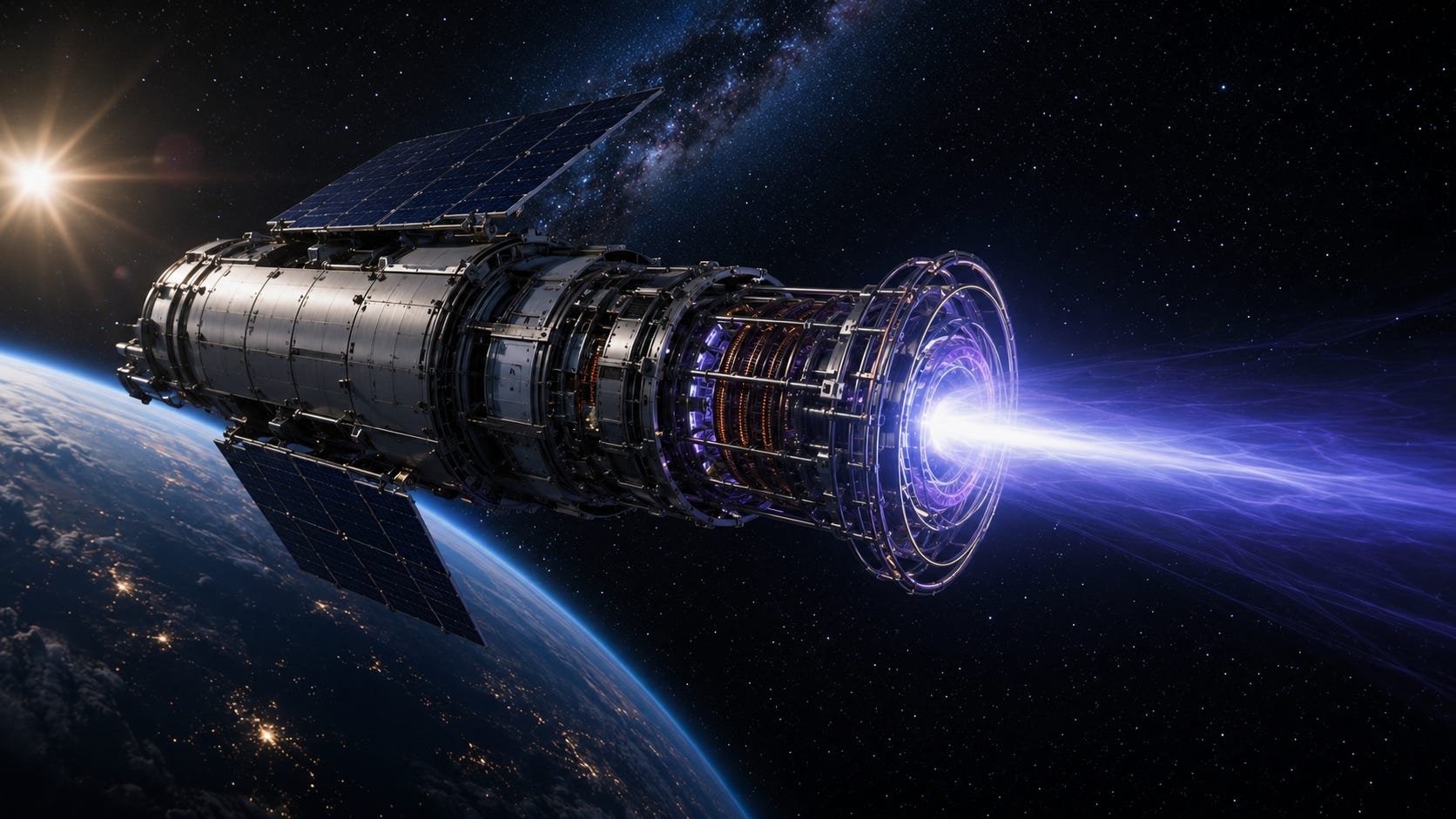
Technology and program status current through July 2026.
Radio-frequency plasma propulsion begins with a straightforward chain of energy conversion.
Electrical power → radio-frequency fields → plasma energy → directed exhaust momentum → spacecraft thrust
The spacecraft carries propellant. Radio-frequency electromagnetic fields transfer energy into that propellant, first ionizing it and, in some designs, heating it further. Electric and magnetic fields organize the plasma flow. A nozzle region converts part of the plasma’s internal energy into directed axial motion.
Matter leaves the vehicle backward.
The vehicle gains momentum forward.
The system is still a rocket.
The radio-frequency fields provide energy. The propellant provides reaction mass.
That distinction is the foundation for understanding everything that follows.
RF plasma propulsion does not describe one engine or one level of maturity. Radio-frequency ion thrusters have already flown. Hall thrusters and gridded ion engines have accumulated thousands of operating hours in space. Helicon and electrodeless magnetic-nozzle systems are less mature. VASIMR, the Variable Specific Impulse Magnetoplasma Rocket, is a serious high-power member of that developmental branch.
The physics needed to make thrust is established.
The complete spacecraft required to exploit it at hundreds of kilowatts or megawatts is not.
Radio waves provide energy, not reaction mass
The phrase “radio waves move spacecraft” can create the wrong mental image.
In RF plasma propulsion, the waves are not normally fired backward as the primary exhaust. They deposit energy into a gas carried aboard the spacecraft.
A spacecraft could generate thrust by emitting electromagnetic radiation directly backward, but photon thrust is extremely small for a given power.
For an emitted beam
Photon thrust = power ÷ speed of light
A 200-kilowatt electromagnetic beam would produce approximately
0.00067 newtons
A plasma engine using 200 kilowatts, operating near 70 percent jet efficiency and ejecting propellant at roughly 48 kilometers per second, can produce several newtons instead.
The reason is straightforward. Massive particles moving at nonrelativistic exhaust velocities carry much more momentum per unit energy than photons.
For a conventional rocket exhaust
Thrust = mass flow rate × exhaust velocity
Or
F = m-dot × vₑ
The electromagnetic fields are an internal energy-transfer system.
The gas is the exhaust.
Electric propulsion is a family, not a single machine
“Electric propulsion” includes several physically distinct architectures
Gridded ion thrusters
Radio-frequency ion thrusters
Hall-effect thrusters
Resistojets and arcjets
Magnetoplasmadynamic thrusters
Pulsed plasma thrusters
Pulsed inductive thrusters
Helicon magnetic-nozzle thrusters
VASIMR
They share one broad idea: electrical power is used to increase propellant exhaust velocity.
They do not share the same
Ionization method
Acceleration mechanism
Power range
Erosion mechanism
Lifetime
Thrust density
Plume structure
Flight maturity
Spacecraft integration burden
A radio-frequency ion thruster, for example, uses an RF field to generate plasma but relies on electrostatic grids for most of the final ion acceleration.
VASIMR uses one RF stage to create plasma, another to heat it, and an expanding magnetic nozzle to convert plasma energy into directed exhaust.
Those are not minor variations.
They are different propulsion systems.
RF ion propulsion has already flown
Radio-frequency ion thrusters provide the clearest evidence that RF plasma production is not speculative.
In an RF ion thruster, neutral propellant enters a discharge chamber surrounded by an RF coil. Electrons absorb energy from the oscillating field and ionize the gas. Positive ions are then extracted and accelerated through electrostatic grids. A downstream neutralizer returns electrons to the beam so the spacecraft does not charge negatively and pull the ions back.
ESA’s Artemis communications satellite carried two different gridded ion-propulsion systems: an electron-bombardment system and a radio-frequency ion system. After a launch-stage malfunction left Artemis below its intended orbit, the spacecraft’s ion propulsion was repurposed from station keeping to orbit raising. Artemis ultimately climbed from roughly 31,000 to 36,000 kilometers using the low-thrust system, demonstrating how cumulative electric propulsion can rescue a mission when chemical propellant is insufficient.
That mission proved several things at once
RF plasma generation can operate aboard a spacecraft.
Low thrust can produce major orbital changes if applied long enough.
Electric propulsion can rescue a mission that would otherwise be lost.
Flight heritage must be assigned to the correct architecture.
Artemis does not prove that VASIMR is flight-ready.
It proves that RF ionization can be part of an operational propulsion system.
Why electric propulsion exists
Chemical rockets are extremely good at releasing enormous power quickly.
They can produce thousands, hundreds of thousands, or millions of newtons because the energy source and reaction mass are stored together and consumed rapidly. That gives chemical propulsion exceptional thrust-to-mass ratio and makes it indispensable for
Launch
Landing
Rapid orbital injection
Emergency maneuvers
High-acceleration departure
Operations deep inside gravity wells
Its main limitation is exhaust velocity.
High-performance chemical engines typically reach effective exhaust velocities of a few kilometers per second, corresponding to specific impulses of several hundred seconds.
Electric propulsion separates the energy source from the propellant.
Instead of depending only on the chemical energy contained in each kilogram of propellant, the spacecraft can continuously add electrical energy to a much smaller mass flow. Exhaust velocities of tens of kilometers per second become practical.
BepiColombo’s gridded ion thrusters accelerate xenon ions to about 50 kilometers per second, roughly 15 times the exhaust velocity ESA cites for conventional chemical thrusters. The vehicle converts power from two 15-meter solar-array wings into sustained thrust during its transfer to Mercury.
That difference can radically reduce the propellant needed for a high-delta-v mission.
It does not eliminate the cost.
The cost moves into
Power generation
Power processing
Thermal rejection
Longer burn times
Lower acceleration
Engine life
Spacecraft integration
Electric propulsion trades propellant mass for power-system mass, time, and complexity.
The equations that control the trade
Only a few relationships are needed to understand why electric propulsion behaves so differently from chemical propulsion.
Thrust
F = m-dot × vₑ
Where
F is thrust
m-dot is propellant mass flow rate
vₑ is effective exhaust velocity
Jet power
Pjet = ½ × m-dot × vₑ²
Combining the two
Pjet = F × vₑ ÷ 2
If a fraction η of the input electrical power becomes useful axial jet power
F = 2 × η × Pin ÷ vₑ
This exposes the central electric-propulsion trade.
At fixed power
Raising exhaust velocity lowers propellant consumption.
Raising exhaust velocity also lowers thrust.
Lowering exhaust velocity raises thrust.
Lowering exhaust velocity increases propellant consumption.
There is no free operating point that maximizes both thrust and exhaust velocity.
Specific impulse is not efficiency
Specific impulse is related to exhaust velocity
Isp = vₑ ÷ g₀
An exhaust velocity of approximately 48 kilometers per second corresponds to an Isp near 4,900 seconds.
Specific impulse measures propellant economy.
It does not directly measure
Electrical efficiency
Thrust
Trip time
Engine mass
Radiator mass
Power-system mass
Lifetime
Cost
A thruster can have very high specific impulse and still be a poor choice for a particular mission because its thrust is too low for the available power.
A lower-Isp electric engine can sometimes complete a mission faster because it converts the same power into more thrust.
NASA’s Mars transportation studies reflect exactly this kind of systems trade. The reference nuclear-electric concepts paired low-thrust propulsion for interplanetary work with chemical propulsion for rapid maneuvers near Earth and Mars. The design problem was not simply maximizing Isp. It was balancing power, thrust, mission time, and total vehicle mass.
The best exhaust velocity is mission-dependent.
A useful 200-kilowatt example
The published high-power VX-200 VASIMR result reported
Total coupled RF power: approximately 200 kilowatts
Thrust: 5.8 ± 0.4 newtons
Specific impulse: 4,900 ± 300 seconds
Thruster efficiency: approximately 72 percent, with uncertainty dependent on the diagnostic and analysis method
Those values came from plume momentum measurements and supporting diagnostics in a ground-test chamber.
At 5.8 newtons, a 100-metric-ton spacecraft would accelerate at approximately
0.000058 meters per second squared
That is about six millionths of Earth gravity.
At that rate, the spacecraft would need nearly five hours to gain just 1 meter per second, but continuous operation would add roughly 5 meters per second every day.
If the same thrust continued for one year under idealized assumptions
Annual delta-v ≈ 1.8 kilometers per second
For a 10-ton spacecraft, the same thrust would produce ten times the acceleration.
These calculations assume
Continuous full power
Constant thrust direction
No eclipses
No engine downtime
No trajectory losses
Approximately constant spacecraft mass
Real trajectories are more complicated.
The example shows why a few newtons can matter in space.
It also shows why a few newtons do not behave like a chemical rocket burn.
Propellant selection is an engineering trade
Electric-propulsion systems often use noble gases because they are chemically inert and relatively straightforward to handle in a plasma discharge.
The main candidates include xenon, krypton, and argon.
Xenon
Xenon is widely used in Hall and gridded ion thrusters because it is
Heavy
Chemically inert
Relatively easy to ionize
Dense enough for compact storage
Well understood in mature propulsion systems
Its disadvantages include cost, supply limitations, and the production scale required for very large fleets or high-propellant-mass missions.
Krypton
Krypton is lighter and generally less favorable for storage density than xenon, but it is cheaper and can be attractive for commercial fleets.
In published VX-200 experiments, krypton showed lower ionization energy cost per extracted ion than argon in the tested helicon configuration and provided a wider efficient operating envelope in some regimes.
Argon
Argon is abundant and inexpensive, which makes it attractive for high-throughput systems.
It is lighter and less dense than xenon, and it requires more energy to ionize. Those penalties affect
Tank volume
Feed-system design
Ionization efficiency
Thrust at a given operating point
Mission optimization
Ad Astra has emphasized argon for much of its VASIMR work, while the architecture can operate with several gases depending on mission and source design.
No propellant is best in every category.
The correct choice depends on the mission.
From neutral gas to plasma
Neutral gas enters the discharge chamber at low pressure.
An RF antenna generates an oscillating electric field. Free electrons absorb energy from that field. When an electron collides with a neutral atom with sufficient energy, it can remove another electron:
electron + neutral atom → positive ion + two electrons
Repeated collisions sustain a partially ionized plasma containing
Ions
Electrons
Neutral atoms
Excited atoms
Electromagnetic waves
Electric potentials
Density gradients
Temperature gradients
Propulsion plasmas are frequently far from thermal equilibrium.
Electrons may be much more energetic than ions. Ion temperature can differ between motion parallel and perpendicular to the magnetic field. The particle distributions may not follow a simple thermal curve.
This is why “the plasma temperature” is often an incomplete description.
What a helicon source does
A helicon source is a particular RF plasma source operated in a magnetic field.
Under suitable conditions, the antenna excites waves related to the whistler family. These waves can couple energy efficiently into electrons and support dense plasma production.
Not every RF discharge is a helicon discharge.
The operating mode depends on
RF frequency
Antenna geometry
Chamber diameter
Magnetic-field strength
Neutral pressure
Plasma density
Boundary conditions
Competing capacitive and inductive modes
A dense plasma source is only the first step.
The system must still
Ionize enough of the injected propellant
Limit wall losses
Transfer additional energy efficiently
Convert internal energy into axial motion
Control plume divergence
Detach the exhaust
Maintain acceptable component temperatures
High plasma density does not automatically equal high propulsion efficiency.
Ionization has a cost
Each atom that becomes an ion consumes energy.
Additional losses can occur through
Excitation without ionization
Radiation
Neutral heating
Electron losses to surfaces
Ion losses to surfaces
Incomplete propellant utilization
RF transmission losses
Reflected RF power
Turbulent transport
Charge exchange
VX-200 measurements reported optimized ionization costs near 80 electron-volts per extracted argon ion and about 70 electron-volts per extracted krypton ion in the tested conditions, despite first-ionization energies being much lower. The difference represents real discharge losses and inefficiencies.
At low exhaust energy, the fixed cost of creating plasma consumes a larger fraction of total power.
At higher exhaust energy, ionization becomes a smaller fraction of the total energy per particle.
But increasing energy per particle lowers thrust at fixed power.
The same trade appears again.
The VASIMR architecture
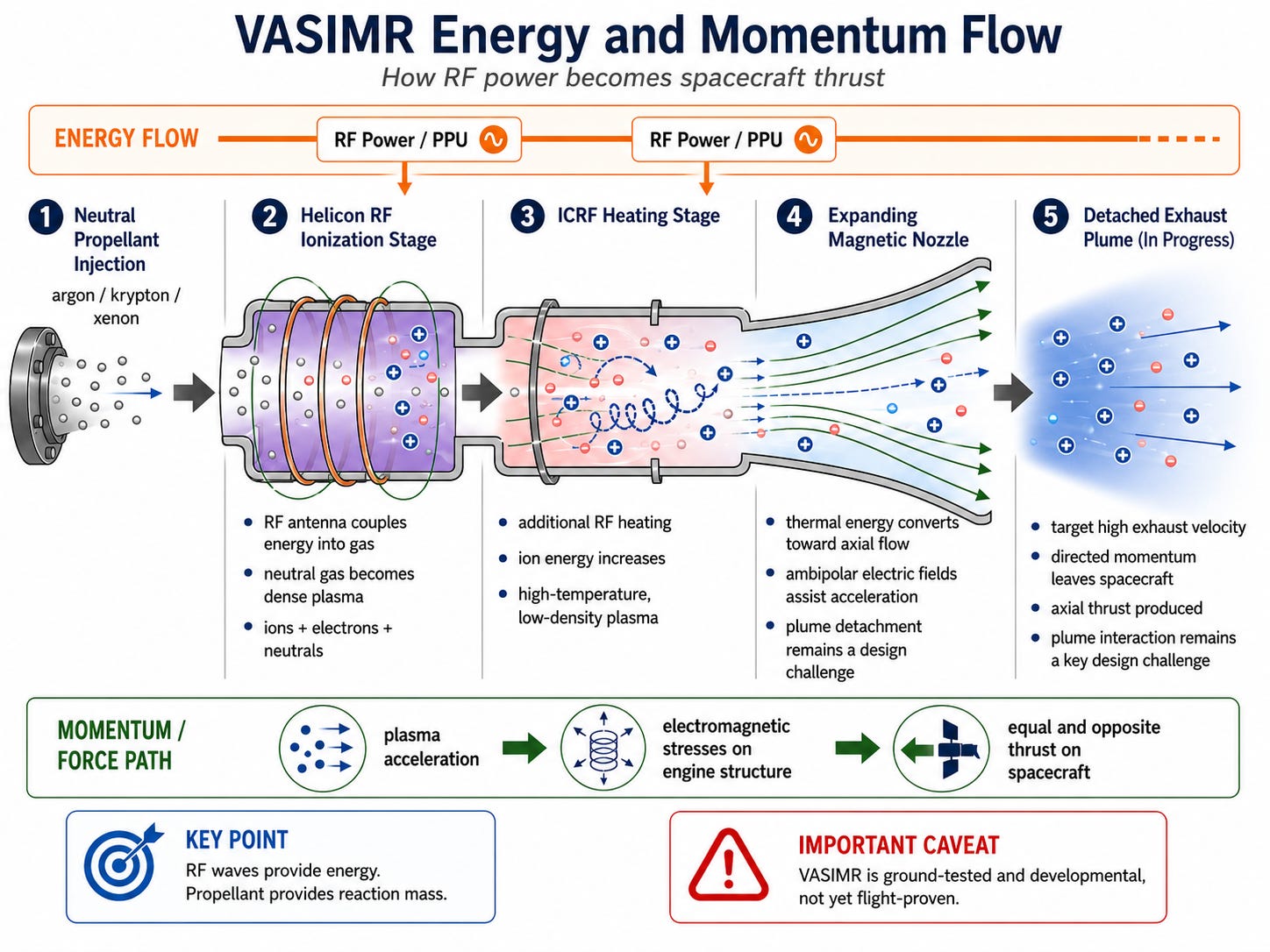
VASIMR divides the engine into three main functional regions.
Stage 1: plasma production
Neutral gas is injected into a magnetized chamber.
An RF coupler creates a dense plasma, commonly described as a helicon-type discharge.
The first stage must produce enough ionized mass flow for the downstream heater without consuming too much of the total power.
Stage 2: ion heating
A second RF coupler transfers additional energy into the plasma.
VASIMR uses heating in the ion-cyclotron range of frequencies, related to techniques used in magnetic-confinement plasma research.
The local cyclotron frequency depends on
charge × magnetic-field strength ÷ particle mass
The actual wave-particle interaction is more complicated than simply matching one frequency. Coupling depends on
Magnetic-field profile
Plasma density
Particle distribution
Ion species
Wave polarization
Resonance location
Energy spread
Transit time through the heating region
Stage 3: magnetic-nozzle expansion
The heated plasma enters an expanding magnetic field.
The nozzle must convert as much plasma energy as possible into directed axial exhaust while limiting
Transverse motion
Plume rotation
Divergence
Backflow
Wall loading
Incomplete detachment
That final step is where the engine becomes more than a plasma heater.
What “millions of degrees” means
VASIMR descriptions often refer to plasma temperatures in the million-kelvin range.
That can be physically meaningful, but it is easy to misunderstand.
In plasma physics, temperature is often used to express average particle energy. One electron-volt corresponds to roughly 11,600 kelvin. A particle population with hundreds of electron-volts of characteristic energy can therefore be described as having an effective temperature of millions of kelvin.
That does not mean the engine contains a dense million-degree gas resembling a furnace.
Heat transfer depends on
Particle density
Particle flux
Energy distribution
Contact time
Radiation
Surface geometry
Magnetic insulation
Collision rate
A low-density plasma can have highly energetic particles while delivering a manageable total heat flux.
Manageable does not mean negligible.
In 2025, Ad Astra reported that its RF couplers may need to remove approximately 10 to 15 percent of engine power as waste heat. A redesigned coupler reduced steady-state operating temperature by as much as 28 percent during sustained plasma testing. Those are developer-reported results, not independent flight validation, but they directly identify thermal handling as an active design limit.
Plasma temperature and component temperature are not the same quantity.
They are not independent either.
A static magnetic field does no direct work
The magnetic part of the Lorentz force is perpendicular to particle velocity.
That means a static magnetic field changes the direction of a charged particle’s motion but does not directly increase its kinetic energy.
In compact form
magnetic force = charge × velocity × magnetic field
Because the magnetic force is perpendicular to velocity:
velocity · magnetic force = 0
So where does the axial energy come from?
From a combination of
RF electric fields
Plasma-pressure gradients
Ambipolar electric fields
Electron pressure
Magnetic-moment effects
Energy exchange between parallel and perpendicular motion
Induced plasma currents
Expansion through the magnetic geometry
The magnetic field organizes the conversion.
It is not the energy source.
Where the reaction force enters the spacecraft
A rocket must transmit force into its structure.
In a chemical engine, gas pressure acts on chamber and nozzle walls.
In a magnetic-nozzle system, part of the load path is electromagnetic.
Plasma currents interact with the applied magnetic field. The coils producing that field are attached to the engine. The electromagnetic stresses are transmitted through the magnet supports and spacecraft structure.
Other contributions can include pressure on upstream boundaries and forces associated with plasma expansion.
The engine is not pushing against empty space.
It is pushing against its own propellant through an electromagnetic load path.
The magnetic nozzle has three separate jobs
A useful way to evaluate magnetic-nozzle performance is to separate three functions.
1. Energy conversion
The nozzle must convert plasma internal energy and transverse particle energy into directed axial kinetic energy.
Heating the plasma is not enough.
Energy left in
Random motion
Rotation
Transverse velocity
Thermal spread
does not contribute fully to useful thrust.
2. Collimation
The exhaust must point backward.
If a particle leaves at angle θ, only the axial component contributes fully
Useful axial velocity = total velocity × cos θ
Published VX-200 plume measurements reported divergence half-angles around 18 to 20 degrees under the tested conditions.
A plume can have high particle energy and still waste power sideways.
3. Detachment
The exhaust must separate from the applied magnetic geometry and continue downstream.
Ions and electrons do not necessarily detach at the same location or through the same mechanism.
Relevant processes can include
Loss of adiabaticity
Finite Larmor radius
Resistive diffusion
Charge exchange
Recombination
Inertial effects
Current closure
Magnetic reconnection
Self-field effects
Detachment is not one switch that turns on at the end of the nozzle.
It is a regime-dependent plasma process.
Detachment is not fully solved
Magnetic field lines are not physical pipes, but strongly magnetized particles can remain dynamically coupled to them.
As the field weakens downstream
Ion gyroradii increase.
Ions may demagnetize.
Electrons may remain magnetized longer.
Electric fields can keep the species coupled.
Plasma currents can alter the field.
Charge-exchange collisions can create uncontrolled fast neutrals.
Turbulence can increase cross-field transport.
VX-200 experiments have reported evidence consistent with detachment occurring within several meters of the nozzle in the tested chamber and operating regime. That is meaningful evidence, but it does not close the problem across every power level, propellant, magnetic topology, and flight condition.
The accurate conclusion is
Detachment can occur, but its efficiency and behavior across the flight envelope still have to be demonstrated.
Plasma still touches hardware
An electrodeless design removes electrodes from direct exposure to the hottest central flow.
That can eliminate important erosion mechanisms found in Hall and gridded ion thrusters.
It does not create a material-free engine.
The plasma source still contains
RF windows
Ceramic tubes
Gas injectors
Structural supports
Seals
Endplates
Transmission hardware
Thermal interfaces
Particles can reach those surfaces through
Cross-field diffusion
Turbulence
Charge exchange
Edge transport
Collisions
Imperfect confinement
Ad Astra’s steady-state work discusses plasma-facing ceramic assemblies, endplates, seals, temperature measurements, and active cooling. Research associated with the system has also examined plasma-surface interaction directly.
The defensible claim is
VASIMR removes acceleration grids and embedded main-flow electrodes, potentially reducing major lifetime-limiting erosion mechanisms.
The indefensible claim is
The plasma never touches the engine.
Efficiency is a chain
A plasma engine does not convert spacecraft electrical power directly into perfectly axial exhaust.
Energy passes through multiple stages
Primary electrical generation
Power conditioning and distribution
RF generation
RF transmission and impedance matching
Plasma coupling
Ionization
Ion heating
Magnetic-nozzle conversion
Plume collimation
Useful axial exhaust
Every stage has losses.
A conceptual total efficiency includes
Power-processing efficiency
RF transmission efficiency
Coupling efficiency
Ionization efficiency
Propellant-utilization efficiency
Heating efficiency
Nozzle efficiency
Divergence efficiency
Auxiliary power
A quoted thruster efficiency may not include
Reactor conversion losses
Solar-array losses
Cryocooler power
Magnet power
Pump power
Thermal-control power
PMAD losses
The mission-relevant quantity is bus-to-axial-jet efficiency.
That number belongs to the complete propulsion string, not only the plasma core.
Propellant utilization matters
Not all injected gas necessarily becomes useful high-speed exhaust.
Some can leave as
Slow neutrals
Partially heated neutrals
Low-energy ions
Off-axis ions
Backstreaming particles
Wall losses
Poor propellant utilization reduces effective performance and can increase charge exchange.
In a charge-exchange collision, a fast ion can become a fast neutral. That fast neutral is no longer controlled by the magnetic field and can strike surfaces downstream.
High ionization fraction helps.
It does not by itself prove high axial momentum efficiency.
The full injected mass flow must appear in the momentum and energy accounting.
How thrust is measured
High-power electric-thruster performance can be measured using
Mechanical thrust stands
Plasma momentum-flux sensors
Faraday probes
Retarding-potential analyzers
Calorimetry
Mass-flow measurements
Integrated plume diagnostics
Electrical power accounting
Each method measures a different part of the system.
The published VX-200 high-power result used a plasma momentum-flux sensor scanned across the plume. The measured force density was integrated under an assumption of approximate azimuthal symmetry. Supporting diagnostics were used to estimate specific impulse, plume behavior, and efficiency.
That method is technically legitimate.
It is still important to distinguish
Direct vehicle-level mechanical thrust
Integrated plume momentum
Derived thrust from power and mass flow
Modeled performance
Future flight validation should reconcile all of them.
What VX-200 demonstrated
At approximately 200 kilowatts of coupled RF power, VX-200 produced a reported 5.8 ± 0.4 newtons of thrust at 4,900 ± 300 seconds of specific impulse.
The published result also reported approximately 72 percent thruster efficiency and a plume divergence half-angle around 18 to 20 degrees in the measured regime.
That is the central VX-200 performance result.
It shows that VASIMR is not merely a plasma-source experiment. The system produced measurable thrust at high power with exhaust velocity far above chemical propulsion.
The engine also demonstrated constant-power throttling over a broad Isp range. The highest thrust-to-power point did not occur at the highest-Isp setting, which is exactly what the power equations predict.
But the high-power runs were short.
The earlier VX-200 configuration had limited thermal management and relied on short pulses with cooldown periods between runs. Some plume measurements were taken during selected time windows to minimize the influence of rising background-gas pressure in the chamber.
The result demonstrates performance.
It does not demonstrate mission life.
What the 88-hour run demonstrated
VX-200SS was built to address thermal steady-state operation.
In July 2021, the engine operated continuously for 88 hours at approximately 80 kilowatts. The system reached thermal equilibrium and demonstrated sustained operation of the plasma source, active cooling, controls, and vacuum-compatible RF power-processing hardware.
That was a real engineering milestone.
It was not
88 hours at 200 kilowatts
88 hours at 4,900 seconds Isp
A mission-lifetime test
A flight-qualified configuration
A complete erosion qualification
The endurance campaign encountered sporadic RF-circuit transients at higher steady-state power. The controls interrupted and restarted the second RF stage without extinguishing the plasma. The intended 100-hour run ended at 88.1 hours after a faulty sensor triggered shutdown.
That does not invalidate the run.
It shows what sustained testing is supposed to reveal.
Short pulses prove that a system can reach an operating point.
Long tests reveal whether the surrounding hardware can live there.
Eighty-eight hours is not deep-space lifetime
Operational electric-propulsion missions routinely require thousands of hours.
Deep Space 1’s ion engine operated for 16,265 hours and delivered about 4.3 kilometers per second of delta-v.
SMART-1 accumulated nearly 5,000 hours of Hall-thruster operation and produced about 3.5 kilometers per second of delta-v during its lunar mission.
The NEXT development program completed a 48,000-hour ground life test.
For VASIMR to establish mission-class life, testing must eventually cover
Thousands to tens of thousands of hours
Thermal cycling
Repeated starts and stops
RF arcing
Magnet cycles
Cryocooler wear
Valve cycles
Contamination
Structural fatigue
Radiation
Launch vibration
Post-test inspection
Quantified erosion
The next meaningful threshold is not another visually impressive firing.
It is a statistically credible lifetime campaign.
Current VASIMR status through July 2026
NASA TechPort described VASIMR in January 2026 as a high-power electric-propulsion system “approaching TRL 5.”
Ad Astra’s April 2025 release described the system as being around TRL 4 to 5 and reported a redesigned RF coupler that reduced steady-state temperature by as much as 28 percent. The same release said the existing couplers worked well near 80 kilowatts but approached thermal limits at higher continuous power. These are company-reported maturation results.
In October 2025, Ad Astra announced a two-year, $4 million NASA contract focused on
The first-stage RF subsystem
The superconducting magnet subsystem
The structural exoskeleton
NASA’s own SBIR page lists Ad Astra’s “Technology Maturation of the VASIMR Electric Propulsion System” among its 2025 Phase II Sequential awards.
The company also announced a four-year VF-150 program intended to build two 150-kilowatt engines. Its published schedule called for an engineering pathfinder in 2028 and a second engine intended for orbital flight testing after completion in 2029. Those are company targets, not completed milestones.
The accurate status is
VASIMR is an advanced, high-power, ground-tested electric-propulsion system at or approaching TRL 5, with subsystem maturation and a proposed orbital demonstration path, but no flight heritage as of July 2026.
How it compares with the strongest alternatives
The relevant comparison is not VASIMR versus old ion engines.
It is VASIMR versus mature and advancing electric-propulsion families.
VASIMR VX-200
Power: approximately 200 kW at the high-performance point
Thrust: 5.8 ± 0.4 N
Isp: 4,900 ± 300 s
Efficiency: approximately 72 percent thruster efficiency
Maturity: high-power ground demonstrator
Flight heritage: none
Strongest evidence: high-power plume performance and a separate 88-hour steady-state campaign
Main open issues: continuous full-power thermal operation, lifetime, flight magnet, plume integration, qualification
X3 nested-channel Hall thruster
Power: tested up to 102 kW
Maximum measured thrust: 5.42 N
Demonstrated Isp range: approximately 1,800 to 2,650 s
Total efficiency: approximately 54 to 67 percent across the reported test envelope
Maturity: high-power laboratory demonstrator
Flight heritage: none
Main strength: high thrust-to-power at Hall-thruster exhaust velocities
Main issues: cathode life, channel erosion, plume behavior, scaling and integration
AEPS Hall propulsion system
Power: approximately 12.5 kW per thruster
Thrust: more than 580 mN
Propellant: xenon
Architecture: magnetically shielded Hall thruster, power-processing unit, and flow controller
Maturity: flight-system development for Gateway
Main strength: flight-oriented production and qualification path
Main limitation: much lower power per unit, requiring clustering for very high total power
NEXT-class gridded ion propulsion
Power: kilowatt class
Thrust: hundreds of millinewtons
Isp: several thousand seconds
Maturity: extensive development heritage
Lifetime evidence: 48,000-hour ground life test
Main issues: grid erosion, neutralizer dependence, space-charge limits, lower thrust density
Chemical propulsion
Power delivery: extremely high and stored internally in propellant chemistry
Thrust: thousands to millions of newtons
Isp: typically hundreds of seconds
Maturity: fully operational
Main strength: thrust density
Main limitation: propellant mass for high-total-delta-v missions
This comparison shows why no single number settles the competition.
VASIMR’s high-Isp point uses roughly twice the power of X3 for comparable thrust because it ejects less mass at much higher velocity.
That is not a defect.
It is the power-exhaust-velocity trade in action.
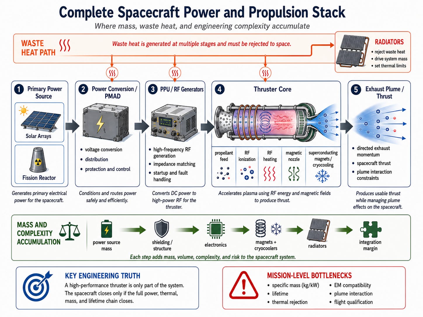
Figure 2. The complete spacecraft power and propulsion stack. A high-performance thruster is only one subsystem. Power generation, conversion, RF electronics, magnets, cryogenic cooling, radiators, structure, lifetime, electromagnetic compatibility, and plume integration determine whether the vehicle closes at the mission level.
The power plant controls the mission
A thruster converts electrical power into exhaust momentum.
It does not generate the electricity.
A 200-kilowatt engine requires at least 200 kilowatts delivered to the propulsion chain, plus additional power for
Avionics
Communications
Guidance
Cryocooling
Pumps
Valves
Thermal control
Payloads
Life support
Contingency margin
A multi-engine transportation vehicle can require megawatts.
At that scale, the spacecraft becomes a power and thermal system with a propulsion core attached.
Solar-electric power
Solar electric propulsion is already operational.
Its advantages include
No reactor
No fission-product shielding
Mature photovoltaic technology
Modular scaling
Direct electrical output
Strong performance in the inner solar system
Its limitations include
Power decreasing approximately with the inverse square of distance from the Sun
Large array area
Deployment complexity
Radiation degradation
Micrometeoroid exposure
Pointing constraints
Eclipse interruptions
Structural flexibility
Plume interaction
BepiColombo is a real example of solar-electric propulsion operating at interplanetary scale. Its arrays supply the power for long-duration xenon ion thrusting during the Mercury transfer.
Solar power can support substantial electric propulsion.
The hard question is whether a megawatt-class array can be made light, stiff, deployable, durable, and compatible with the vehicle’s plume and thermal geometry.
Nuclear-electric power
Nuclear-electric propulsion does not use reactor heat directly as rocket exhaust.
The reactor produces heat.
A conversion system turns part of that heat into electricity.
The electricity powers electric thrusters.
The unused heat must be rejected to space.
A complete nuclear-electric system requires
Reactor
Control system
Shielding
Primary heat transport
Power conversion
Power management and distribution
Radiators
Thrusters
Propellant
Structural booms
Fault protection
NASA’s Mars studies examined hybrid architectures that used nuclear-electric propulsion for long-duration interplanetary work and chemical propulsion for high-thrust maneuvers. The studies treated reactor cooling, power conversion, radiator deployment, and total specific mass as first-order mission variables.
The correct competition is not always electric versus chemical.
Often the best answer is electric plus chemical, each used where it performs best.
Waste heat may dominate the design
No practical power system is perfectly efficient.
If a reactor generates thermal power and only a fraction becomes electricity, the rest must be rejected.
If the thruster converts only part of the electricity into axial jet power, those losses must also be rejected.
In space, heat ultimately leaves by radiation
Radiated power = emissivity × Stefan-Boltzmann constant × area × temperature⁴
Higher radiator temperature reduces area.
But higher temperature demands
Better materials
Hotter working fluids
More difficult pumps
More demanding seals
Higher thermal stress
More difficult power converters
NASA’s megawatt-class Mars studies identified radiator development, deployment, integration, and packaging as major system constraints. In the examined 1.9-megawatt concepts, radiator area reached the scale of thousands of square meters. That number is architecture-specific, but the system lesson is broader.
A megawatt-class propulsion system needs a megawatt-class heat-rejection strategy.
Radiators are not accessories.
They can define the spacecraft.
Present space-reactor capability is far below megawatt transport needs
Modern space-fission development remains far below the multi-megawatt complete power systems assumed in ambitious human-transport studies.
The scale gap is not just reactor-core output.
It includes simultaneous advances in
Heat transport
Power conversion
Long-life rotating machinery or alternative converters
Shielding
Radiators
PMAD
Fault tolerance
Launch safety
Environmental qualification
A compact reactor core does not solve the mission by itself.
The full power-conversion and thermal system must achieve a low enough mass per kilowatt.
Specific mass decides whether the vehicle closes
A critical quantity is
System specific mass = complete power and propulsion mass ÷ electrical power
Usually expressed in kilograms per kilowatt.
For a 10-megawatt system
At 20 kg/kW, system mass is 200 metric tons.
At 5 kg/kW, system mass is 50 metric tons.
That difference can decide whether a mission is possible.
For a spacecraft of mass M
Acceleration = 2 × efficiency × power ÷ M ÷ exhaust velocity
Acceleration therefore depends strongly on
power ÷ total spacecraft mass
A spectacular high-Isp engine attached to an overweight power system can produce an unimpressive spacecraft.
Superconducting magnets are not free
VASIMR relies on strong magnetic fields.
Superconducting magnets can reduce resistive losses, but they add
Superconducting windings
Structural reinforcement
Cryocoolers
Thermal isolation
Quench detection
Quench protection
Radiation tolerance
Launch qualification
Magnetic shielding
Redundant cooling
Published VX-200 development work describes cryogenic superconducting magnets and substantial laboratory cryocooler requirements. A future flight system would have to reduce that burden while retaining field strength, reliability, and quench protection.
A superconducting coil may have nearly zero electrical resistance.
The cooling system does not consume zero power.
PMAD and RF power processing are part of the engine
Power does not move directly from a solar array or reactor into the plasma.
The spacecraft requires
Voltage conversion
Distribution
Switching
Fault protection
RF generation
Impedance matching
Arc detection
Startup sequencing
Restart logic
Thermal control
Electromagnetic shielding
VX-200SS used vacuum-compatible RF power-processing hardware and demonstrated automatic recovery from RF-stage interruptions during the long-duration test. That is real engineering progress, but it also shows that the engine includes much more than the glowing plasma chamber.
At one megawatt
A 1 percent loss is 10 kilowatts.
A 5 percent loss is 50 kilowatts.
Small percentages become large radiators.
The spacecraft must survive its own electromagnetic environment
A high-power RF plasma engine is also a strong electromagnetic source.
The vehicle must control
RF interference
Harmonics
Coupling into avionics
Magnetometer contamination
Induced structural currents
Solar-array interaction
Sensor saturation
Magnetic torque
Charging
Interaction between clustered engines
This can influence
Cable routing
Shielding
Boom length
Instrument placement
Attitude constraints
Engine clustering
The engine can function perfectly in isolation and still be unacceptable for the spacecraft.
Plume integration can determine the layout
The exhaust plume can interact with
Solar arrays
Radiators
Antennas
Optical surfaces
Thermal blankets
Docked vehicles
Crew modules
Scientific instruments
Possible consequences include
Sputtering
Surface charging
Heating
Optical contamination
Array degradation
Sensor interference
Torque
Communication noise
A high-power engine may require
Long booms
Keep-out angles
Dedicated firing attitudes
Shielded surfaces
Restricted docking geometry
The vehicle must be designed around the plume, not merely equipped with it afterward.
Ground testing is not space
High-power plasma testing requires enormous vacuum facilities.
The chamber must remove propellant fast enough to prevent background gas from changing
Charge exchange
Plume divergence
Slow-ion production
Backflow
Thrust measurement
Surface sputtering
VX-200 experiments used a large vacuum chamber, substantial pumping, and carefully selected measurement windows to reduce neutral-pressure effects.
The chamber walls can still influence
Magnetic topology
Plasma return currents
Neutral density
Deposited material
Diagnostic readings
Ground testing is essential.
Orbital testing is still required.
Low thrust changes the trajectory
Electric propulsion does not simply reproduce a chemical burn more slowly.
Chemical burns can often be approximated as impulsive velocity changes.
Low-thrust trajectories evolve continuously while the spacecraft moves.
When climbing from low Earth orbit, electric propulsion can require
Long spirals
Repeated radiation-belt passages
Repeated eclipses
Continuous navigation
Collision avoidance
Extended crew exposure
Greater sensitivity to shutdowns
NASA’s Mars transportation work explicitly treated long gravity-well transit times as a limitation of low-thrust propulsion and used high-thrust stages for rapid departure and capture.
Electric propulsion is often most valuable after another system has already paid the cost of leaving the deepest part of the gravity well.
The Mars question
Could high-power electric propulsion shorten Mars transit?
Under some future power-to-mass assumptions, yes.
Can today’s VASIMR hardware take a crew to Mars in a few weeks?
No.
Transit time depends on the full system
Vehicle mass
Electrical power
Specific mass
Exhaust velocity
Thrust
Departure orbit
Escape strategy
Arrival capture
Crew shielding
Radiators
Propellant
Engine life
Abort options
Planetary alignment
NASA has studied conceptual hybrid nuclear-electric vehicles around 1.9 megawatts, but those complete mission architectures were still measured in hundreds of days and faced steep mass penalties as trip time was reduced.
Extremely short Mars claims generally assume power systems, radiator performance, and specific masses that do not yet exist as flight hardware.
The trajectory equations may close.
The vehicle does not yet exist.
In-situ propellant is not automatically cheap
Mars contains argon, but only as a minor atmospheric constituent.
Using it would require
Atmospheric intake
Gas separation
Compression
Purification
Storage
Transfer
Power
Maintenance
Industrial-scale throughput
The raw material may be local.
The processing infrastructure is not free.
In-situ propellant could eventually support reusable transportation networks, but it should be evaluated using complete energy and mass accounting rather than treated as an automatic advantage.
Where VASIMR may earn its place first
The strongest early applications are likely to be missions where high total delta-v matters more than high acceleration.
Cislunar cargo
Reusable tugs moving cargo between high Earth orbit, lunar orbit, and staging locations can benefit from
High propellant efficiency
Long engine life
Flexible throttling
Reuse
Ad Astra identifies cislunar logistics as the intended commercial market for the planned VF-150 program. That remains a developer objective pending successful hardware completion and flight testing.
Cargo pre-positioning
Habitats, supplies, power systems, and return propellant can be sent ahead of crews.
Cargo can tolerate longer trip times.
Large robotic missions
High-power electric propulsion could support
Heavy orbiters
Sample return
Multi-target asteroid missions
Outer-planet logistics
Large observatories
Reusable in-space transportation
A stage that remains in space avoids atmospheric reentry and can be optimized around
Long life
Refueling
Repeated missions
High cumulative impulse
Planetary defense
With sufficient warning time, high-total-delta-v propulsion may support rendezvous, characterization, or deflection missions.
These are credible mission classes.
They are not guaranteed markets.
What must happen before VASIMR is operational
A serious readiness path requires the following.
1. Continuous high-power operation
Demonstrate the 150-to-200-kilowatt class at thermal steady state with flight-representative hardware.
2. Complete energy accounting
Publish, at the same operating point
Bus power
PPU output
RF coupling
Plasma energy
Axial jet power
Plume divergence
Cryocooler power
Magnet power
Cooling loads
Measurement uncertainty
3. Mission-class lifetime testing
Operate for thousands of hours with
Calibrated erosion measurements
Thermal cycling
Starts and stops
Fault recovery
Post-test inspection
Component replacement accounting
4. Flight-representative magnet qualification
Include
Mass
Structure
Cryogenic system
Quench protection
Magnetic cleanliness
Launch loads
5. Nozzle validation
Measure
Energy conversion
Divergence
Backflow
Detachment
Current closure
Spacecraft interaction
6. Environmental qualification
Complete
Vibration
Shock
Thermal vacuum
Radiation
Arcing
Contamination
Storage-life testing
7. Orbital demonstration
Measure in space
Thrust
Efficiency
Charging
Thermal behavior
Restart reliability
Plume effects
Magnetic interaction
8. Full mission competition
Compare complete architectures on
Delivered payload
Launch mass
Trip time
Propellant
Cost
Reliability
Engine count
Lifetime margin
Radiator area
Failure recovery
That is the standard.
Not whether the plasma glows.
Not whether the exhaust is hot.
Not whether one laboratory operating point looks impressive.
The question is whether the transportation system closes.
Final engineering assessment
RF plasma propulsion is established physics.
RF fields can ionize propellant. RF systems can transfer additional energy into magnetized plasma. Magnetic nozzles can convert part of that energy into directed exhaust. RF ion thrusters have flown. Hall and gridded ion propulsion have already transformed satellite operations and deep-space mission design.
VASIMR has produced meaningful laboratory results.
Its strongest published performance point remains approximately
5.8 newtons
4,900 seconds specific impulse
About 72 percent thruster efficiency
200 kilowatts coupled RF power
Its strongest endurance result remains
88 continuous hours
Approximately 80 kilowatts
Thermal steady-state operation
Recent work has improved RF-coupler thermal behavior, and NASA-supported subsystem maturation is now tied to a proposed 150-kilowatt flight-development program.
The remaining problems are substantial
Continuous full-power operation
Thousands of hours of life
RF-coupler heat
Magnetic-nozzle conversion
Plume detachment
Divergence
Surface interaction
Flight magnets
Cryogenic loads
PMAD
Electromagnetic compatibility
Radiator mass
Megawatt power generation
Orbital validation
Mission economics
None of these problems invalidates the technology.
None can be skipped.
The correct conclusion is neither dismissal nor promotion.
It is this.
RF plasma propulsion is already a legitimate branch of spacecraft engineering. VASIMR is a credible high-power development program with measured thrust, high specific impulse, sustained ground operation, and a declared path toward orbital testing. It is not yet a flight-proven engine, and its ultimate value will be decided by the mass, lifetime, thermal performance, reliability, integration burden, and economics of the complete spacecraft around it.
The plasma physics makes the engine possible.
The system engineering decides whether it matters.
(Selected technical sources)
VASIMR performance and engineering
NASA SBIR/STTR: Phase II Sequential Awardees
https://www.nasa.gov/sbir_sttr/phase-ii-sequential/
VASIMR VX-200 Performance Measurements and Helicon Throttle Tables Using Argon and Krypton
https://www.adastrarocket.com/technical-papers-archives/Ben_IEPC11-156.pdf
Improved Efficiency and Throttling Range of the VX-200 Magnetoplasma Thruster
https://www.adastrarocket.com/technical-papers-archives/Ben-JPP-2014.pdf
Steady-State Testing in the VASIMR VX-200SS Project
https://www.adastrarocket.com/wp-content/uploads/2021/12/2021_AIAA_ASCEND_VASIMR.pdf
Recent Progress on the VASIMR Engine
https://www.adastrarocket.com/wp-content/uploads/2022/06/VASIMR_IEPC2022_525-Paper-final.pdf
Ad Astra RF Coupler Thermal-Design Test, April 2025
https://www.adastrarocket.com/wp-content/uploads/2025/04/AdAstra-Release-041525_Final.pdf
Ad Astra $4 Million NASA Technology-Maturation Contract and VF-150 Program, October 2025
https://www.adastrarocket.com/wp-content/uploads/2025/10/Ad-Astra-Rocket-Company-Wins-4M-Nasa-Contract-To-Advance-The-Maturation-Of-The-Vasimr-Electric-Propulsion-System.pdf
NASA TechPort: Improved Thermo-Mechanical Design of the VASIMR RF Coupler
https://techport.nasa.gov/projects/125579
Magnetic-nozzle physics
NASA: Computational Studies of Magnetic Nozzle Performance
https://ntrs.nasa.gov/citations/20140002458
Electric-propulsion fundamentals and competing systems
NASA/JPL: Fundamentals of Electric Propulsion, Second Edition
https://descanso.jpl.nasa.gov/SciTechBook/series4/Electric_Propulsion_2nd_edition.pdf
NASA: High-Power Performance of a 100-kW-Class Nested Hall Thruster
https://ntrs.nasa.gov/citations/20190004993
NASA: 13-kW Advanced Electric Propulsion Flight System Development and Qualification
https://ntrs.nasa.gov/citations/20200000505
NASA: NEXT Thruster Achieves More Than 48,000 Hours of Operation
https://www.nasa.gov/news-release/nasa-thruster-achieves-world-record-5-years-of-operation/
Flight heritage
NASA: Deep Space 1 Mission Record
https://science.nasa.gov/mission/deep-space-1/
ESA: Electric Blue Thrusters Propelling BepiColombo to Mercury
https://www.esa.int/Enabling_Support/Space_Engineering_Technology/Electric_blue_thrusters_propelling_BepiColombo_to_Mercury
ESA: Electric Propulsion on SMART-1
https://www.esa.int/esapub/bulletin/bulletin129/bul129e_estublier.pdf
ESA: Artemis Ion-Propulsion Recovery
https://www.esa.int/Applications/Connectivity_and_Secure_Communications/Ion_propulsion_system_to_the_rescue
Nuclear-electric mission architecture
NASA: Nuclear Power Concepts and Development Strategies for High-Power Electric Propulsion Missions to Mars
https://ntrs.nasa.gov/citations/20210016968
This article took substantial research, verification, and technical editing to produce. If you value long-form engineering work that separates measured performance from marketing claims, consider becoming a paid subscriber. Paid support funds more pieces at this depth.